NAICH Multi-component Waveform Automatic Lightning Impulse Current Generator Test Device
Also Called Name
Multi-component waveform impulse current test device, four-component waveform impulse current device, 4-component waveform impulse current test, D-component waveform impulse current device, multi-component impulse current test, four-component lightning impulse current, component waveform impulse current test, component waveform impulse Current generator device, multi-component lightning impulse current, four-component impulse current generator, component lightning impulse current, component wave lightning impulse, multi-component impulse current test device, component waveform lightning impulse, D-component wave impulse generator
 Equipment Overview
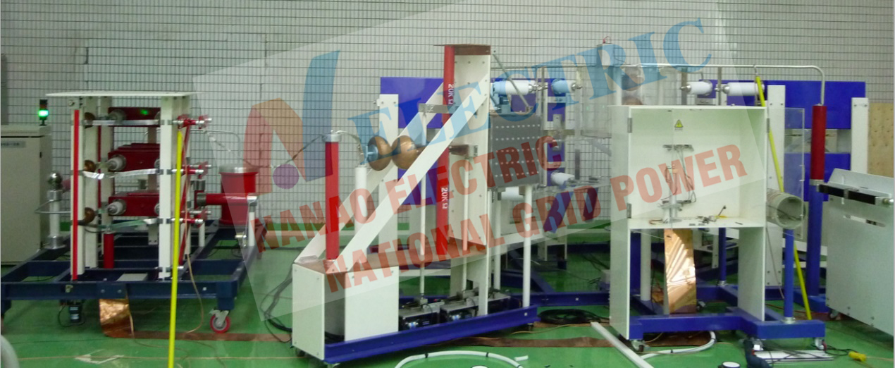
This set of multi-component waveform automatic lightning impulse current generator test device can be used for the lightning protection test of the aircraft, the aircraft's partial cabins or the engine components, and determine the actual induction level and transient waveforms on the aircraft electrical system cables. Determine or verify the transient control level and equipment transient design level related to lightning protection. The generator can also be used to test the non-electrical system conductors of the fuel system (such as control cables, fuel, hydraulic, pneumatic lines and structural parts) or system effects.
The system output D component peak value 100kA, T1≤30μS, T2≤500μS (exponential waveform or oscillating waveform).
According Standards
a) GB 18802.1-2011
b) GB/T 18802.12-2011
c) IEC 61643-1-2011 Low-voltage surge protective devices –Part 1:Surge protective devices connected to low-voltage power distribution systems –Requirements and tests
d) IEC61643-12-2011
e) UL1449-2015 Surge protective devices
f) YD/T 1235.1-2002
g) YD/T 1235.2-2002
h) GB/T 16927.1-1997
i) GB/T 16927.2-1997
j) YD/T 5098-2001
k) GB3567-99
l) GB/T 17626.5-2018
Main Data
Input power: AC, 50Hz/60Hz
Transformer: oil-immersed single-phase, 380V/70kV/10kVA,
Charging voltage: DC80kV, maximum charging current 0.1A
Charging polarity: positive and negative polarity can be changed automatically
Charging time: output 100kA current to charge and discharge once every 60s,
Structure type: Multiple units are arranged in a sector, which can be discharged individually or in combination.
Impact capacitor: 10 impact capacitors
Parameters of high-voltage oil-immersed capacitors: 80kV/2µF
Total impact energy of a single unit: 6.4kJ
Total impact energy of a single unit: 64kJ
Capacitor life: Under normal operating conditions, the rated charge and discharge times of the equipment exceed 200,000 times, and it can be used for a long time under 80% of the rated voltage. When the rated output is running, the reserve margin is greater than 10%.
 Main Components
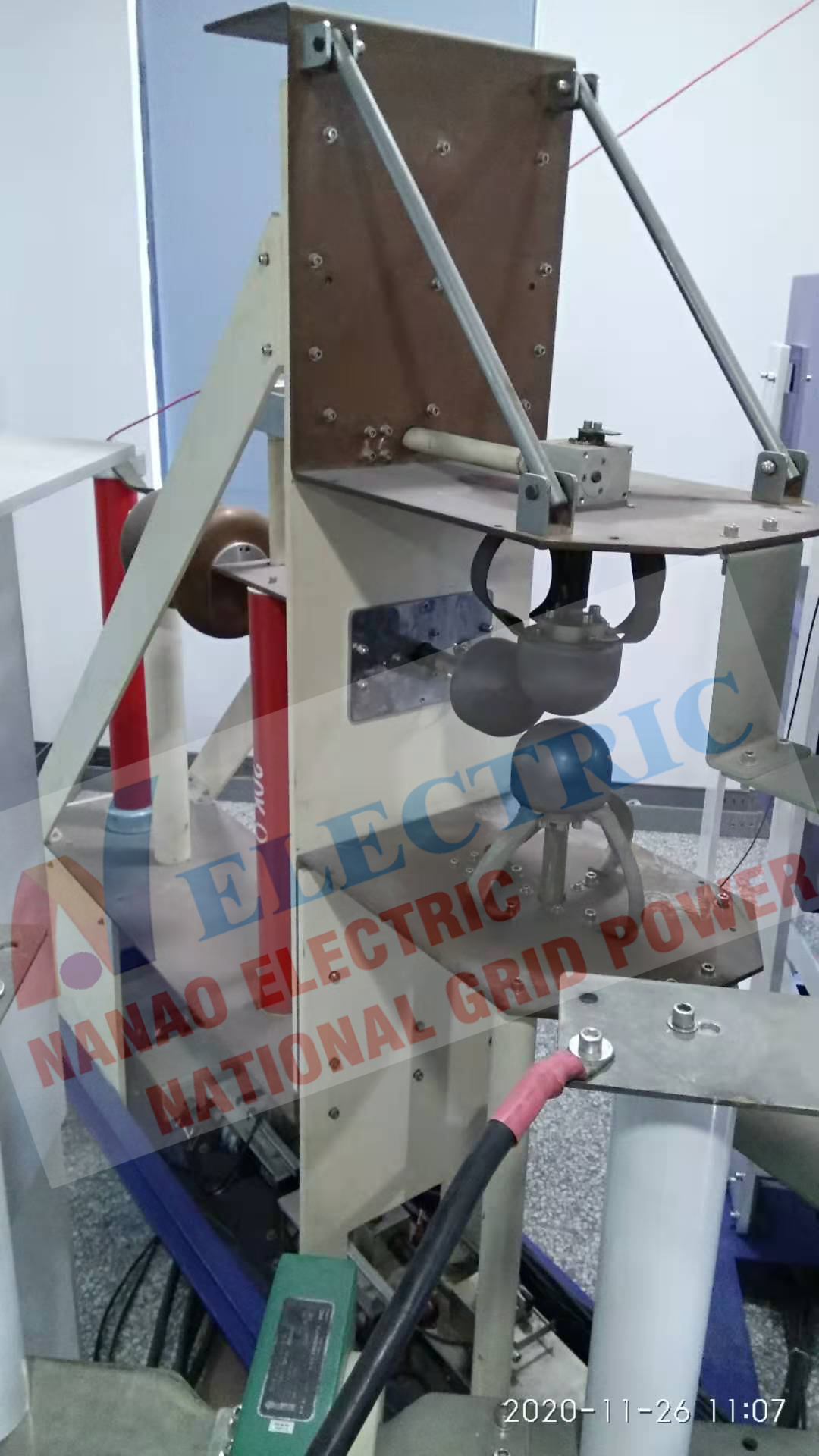
Body Sector Structure
Main Components
Body Sector Structure
The body capacitor adopts a sector structure, capacitor is placed vertically, and bottom is connected and fixed;
The body capacitor adopts a fan-shaped centripetal symmetrical structure to ensure that each group of capacitors is at the same distance from the discharge gap to ensure the uniformity of the discharge current to the greatest extent. In long-term use, such a structural design can ensure the uniform life of the capacitor, thereby prolonging the life of the device.
Capacitors can be operated in a single group or in parallel, and it is more convenient to switch the circuit manually. Each group of capacitors are connected in series with resistors during the discharge process, which can ensure the safe operation of the capacitors.
 简体中文
简体中文 ENGLISH

 ICP No: 42018502003250 Statistics
 (Ms.Allen Cici)
 Skype:nanaoelec