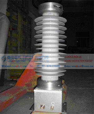
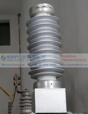
NAPF standard pure resistance lightning high voltage pulse impulse voltage divider
Also name
Pure resistance lightning pulse divider, high voltage pulse impulse divider, pulse voltage divider, pure resistance pulse voltage divider, the standard pure resistor divider, lightning pulse voltage divider, the standard impact voltage divider, high voltage pulse Voltage divider, standard pure resistance lightning high voltage pulse impulse voltage divider
Functional overview
This equipment is equipped with high voltage pulse voltage divider, collecting high frequency and power frequency voltage signal, mainly used for lightning wave measurement, power system overvoltage (operating over voltage, ferromagnetic resonance overvoltage, series resonant overvoltage, etc.) and the system Frequency voltage.
The high voltage pulse divider will serve as a front-end component of the overvoltage on-line monitoring system, providing the relevant attenuator and connected to the overvoltage on-line monitoring system via a dedicated shielded cable for system overvoltage monitoring.
1. a high voltage side
A) a high voltage side of the installation: from the high voltage power grid bus access to the high voltage side of the high voltage arrester and with the high side of the high voltage side of the voltage divider to complete a high voltage side of the installation. The voltage divider is single phase, divided into A, B, C phase, single phase direct connection.
B) can collect high frequency and frequency of the voltage signal.
2. Secondary, measurement monitoring side:
A) secondary monitoring side wiring: the supplier is equipped with a good voltage divider measurement output interface connector, the supplier should be equipped with input attenuator interface connector, the middle is connected to the demand side of the measurement cable signal The attenuator of the line and the supplier forms the measurement loop. Intermediate connection of the measurement cable signal line must be armored flame retardant tape with the measurement cable signal line: coaxial 75-5-1 or 75-5-2 RF shielding cable. Anti-interference ability of the best. Secondary regulator side of the voltage divider Output port connector: Yes SL16 connector. Coaxial.
B) The voltage output of the secondary side of the voltage divider is 500V, and the voltage input to the data acquisition mechanism is 10V. The buffer (attenuator) needs to be installed.
C) Secondary output range: depending on the ratio of the partial pressure ratio. Ratio of large voltage is low, the ratio of small voltage high.
3. lightning high voltage pulse divider works:
Coupled pulse current signal.
Main technical data
1. High voltage pulse divider parameters
Rated voltage: 200kV (0 ~ 200kV) a high voltage side
Rated capacitance: 1000pF
Capacitance section: 1 section
Resistance and inductance: 0 ~ 30Ω, 0 ~ 20uH
Each section capacitance: 1000pF (MWF200kV ~ 1000pF pulse capacitor)
Square wave response: part of the response time is less than 100ns, overshoot less than 10%
Partition ratio: 400: 1
Secondary side of the measurement port Output voltage: 500V (0 ~ 500V)
Partition ratio Uncertainty (measurement accuracy): less than 1%
Installation type: indoor or cabinet installation requirements, synthetic silicone rubber casing insulation shell.
Long-term operation in the 10kV power grid to run, to meet the following waveform monitoring:
A. Standard lightning impulse full-wave voltage waveform
Wave head time: 1.2 ± 30% μs
Tail time: 50 ± 20% μs
Overshoot: less than 5%
Efficiency: no less than 90%
± 1.2 / 50μs standard lightning impulse full-wave, the efficiency is greater than 90%.
B. Standard lightning impulse voltage waveform
Wave head time: 1.2 ± 30% μs
Overshoot: less than 5%
Truncation time: 2 ~ 6μs, electronic delay control
Efficiency: no less than 90%
Using the truncation device can produce truncation time 2 ~ 6μs lightning truncation, truncation dispersion is less than 100ns.
C. Standard operation shock full wave voltage waveform
Wave time: 250 ± 20% μs
Tail time: 2500 ± 60% μs
Efficiency: not less than 80%
± 250 / 2500μs standard operating shock voltage wave, the efficiency is greater than 80%.
D. produces steep wave shock waveforms with steepness greater than 2500 kV / μs
2. attenuator (buffer) parameter
500V / 10V (input / output)
Partition ratio: 50: 1
Attenuator for the voltage divider 10k ohm, to prevent the voltage is too high, can access the monitoring equipment to protect
Attenuator input and output port of the connector: are Q9 connector. Coaxial.
Coaxial connection connector and coaxial shield measurement cable frequency AC voltage and lightning impulse withstand voltage insulation level: ≤ 4kV.
Equipment size
Dimensions: 900Hx300Wx300L (mm), single weight: 15kg.
Installation size: 900Hx250Wx250L (mm)
 简体中文
简体中文 ENGLISH

 ICP No: 42018502003250 Statistics
 (Ms.Allen Cici)
 Skype:nanaoelec